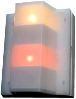
The WM-00 unit is the core of the WM-based call processing system. The various set and reset peripherals are always wired to a WM-00 unit. All WM-00 units in a system are connected by a four-wire bus, trough which calls are transmitted.
The WM-00 unit contains two different lights, one indicating a local call (on one of the 'set' devices connected to this unit), the other indicating a system call (on any 'set' device on any WM-00 unit in the system). Also, the WM-00 is equiped with a buzzer with continuously selectable soundpressure level, tied to the red 'local call' lamp. Any WM-00 unit in the system set to 'master' (see the wiring scheme for details) will also signal with red light and buzzer any time a call is made by any of the 'slave' units.
The WM-00R unit is identical to the WM-00 unit, but it contains a relay with isolated contacts, usable for driving any custom peripheral. The relay can be set with a jumper to either respond along with the red 'local call' light, or the white 'system call' light.
The 130.2900 wall mounting frame is required for mounting a 130.1100/SP to a wall. This part must be ordered seperately.
WM-00 Peripherals
There are two different devices for setting a call. A pull-chain (125.8600S) and a bright-red push-button (125.8120S). Both are identical in function.
There is one unit for resetting (cancelling) a call, a unit with a green button (125.8130S).
Also, auxiliary output relays are available for connecting external devices monitoring the bus.
WM-00 Specifications
WM-00 part# 130.1100/SP Operating voltage 20-30VDC Drawn Current 5mA standby
200mA for each lighted lampCall memory after power fail 600s min WM-00 drive current on hold-line 2 A [*] Relay (on WM-00R only) 2A AC/DC non inductive load Spare red lamp part# 130.9520 Spare white lamp part# 130.9500 [*] Due to the 2A drive current on the WM-00 hold line no more than 10 WM-00 devices on a single bus (without relays) can have a white lamp installed. If more devices are needed on one bus only 10 of them may have the white lamp installed.
The maximum count of WM-00 devices on one bus depends largely on the thickness of the used wiring and the total configuration of the bus.
The WM-00 wiring scheme
Return to the WM-00 indexpage
| Copyright, Innovative Design Delft | site by ii.nl |